Architecture Design
Typical system topology, deployment models, capacity planning, and physical equipment wiring for enterprise-scale audit and forensics platforms.
4.1 Typical System Topology
The reference topology for an enterprise audit and forensics platform is organized around three security zones with clearly defined data flows, trust boundaries, and access control points. This three-zone model has been validated across multiple enterprise deployments and provides the optimal balance between evidence integrity, operational efficiency, and administrative control.
The topology is designed to ensure that all evidence flows are unidirectional from production to security zones, that no production system can directly access or modify evidence storage, and that all administrative access to any zone is mediated through the bastion server in the management zone. This architecture eliminates the most common evidence integrity failure modes: direct admin access to log storage, shared credentials between production and security zones, and unmonitored administrative pathways.
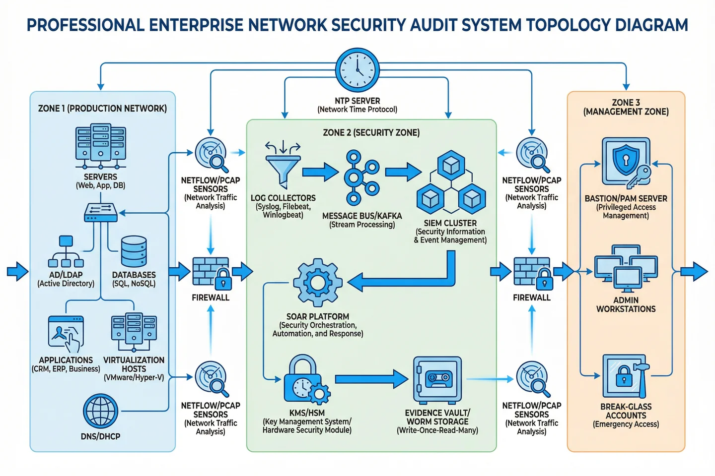
| Zone | Components | Network Segment | Access Control | Data Flow Direction |
|---|---|---|---|---|
| Zone 1: Production | Servers, AD/LDAP, Databases, Apps, DNS/DHCP, Hypervisors | Production VLAN (10.x.x.x/16) | Standard enterprise ACLs; outbound log only | Outbound only → Zone 2 collectors |
| Zone 2: Security | Log Collectors, Message Bus, SIEM, SOAR, Evidence Vault, KMS/HSM | Security VLAN (172.16.x.x/24) | Deny-by-default; inbound log + outbound management only | Inbound from Zone 1; internal pipeline; no outbound to Zone 1 |
| Zone 3: Management | Bastion/PAM, Admin Workstations, Break-Glass Accounts | Management VLAN (192.168.x.x/24) | MFA required; all sessions recorded; admin-only access | Bidirectional to Zone 1 and Zone 2 via bastion only |
4.2 Deployment Models
Three deployment models are supported, each optimized for different organizational profiles and infrastructure constraints. The selection of deployment model determines the physical placement of components, the network architecture requirements, and the operational procedures for evidence collection and management.
| Model | Profile | Architecture | Key Considerations | Recommended Scale |
|---|---|---|---|---|
| Centralized On-Premises | Single DC, high-security environments | All components in dedicated security rack; dedicated security VLAN; physical separation | Lowest latency; highest control; requires dedicated hardware budget | 500–5,000 endpoints |
| Hybrid (On-Prem + Cloud) | Multi-site with cloud workloads | On-prem collectors + cloud-native SIEM; cloud evidence vault (S3/Azure Blob with object lock) | Cloud API integration required; cross-region replication for DR; data residency compliance | 2,000–20,000 endpoints |
| Distributed with Central SOC | Multi-site enterprise; remote branches | Lightweight collectors at each site; WAN-optimized transport to central SIEM; central evidence vault | WAN bandwidth sizing critical; local buffering for connectivity failures; site-level bastion | 5,000–20,000 endpoints |
4.3 Capacity Planning
Accurate capacity planning is essential for ensuring that the platform can sustain evidence collection under all conditions, including peak load events such as security incidents, batch processing windows, and audit periods. The following table provides reference sizing parameters for the three deployment scales supported by this design guide. Use the calculators in Chapter 9 for precise sizing based on your specific environment.
| Parameter | Small (500–2K endpoints) | Medium (2K–8K endpoints) | Large (8K–20K endpoints) |
|---|---|---|---|
| Baseline EPS | 2,000–8,000 EPS | 8,000–32,000 EPS | 32,000–80,000 EPS |
| Peak EPS (incident) | 5× baseline | 5× baseline | 3× baseline |
| Hot Storage (90 days) | 5–20 TB | 20–80 TB | 80–200 TB |
| Cold Archive (7 years) | 50–200 TB | 200–800 TB | 800 TB–2 PB |
| PCAP Retention | 7 days egress only | 14 days egress + critical zones | 30 days multi-zone |
| Collector Nodes | 2 (N+1) | 4–6 (N+1) | 8–16 (N+1 per site) |
| SIEM Index Nodes | 3 (HA cluster) | 6–9 (HA cluster) | 12–24 (HA cluster) |
| Evidence Vault | 2 nodes (mirrored) | 4 nodes (erasure coded) | 6+ nodes (erasure coded) |
4.4 Physical Equipment Wiring & Rack Layout
Physical rack layout and cable management are critical for operational reliability and evidence integrity. Proper cable organization ensures that management, data, and storage networks are physically separated, reducing the risk of accidental cross-connection and simplifying troubleshooting. The reference rack design places all security platform components in a dedicated rack or cage with physical access controls.
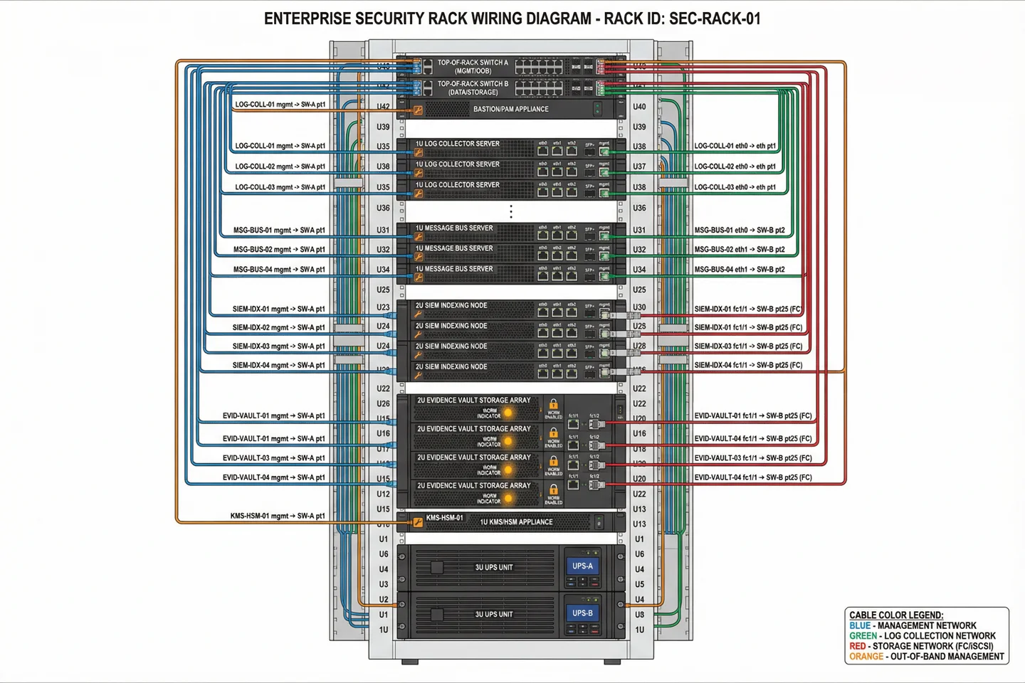
| Cable Type | Color Code | Network | Speed | Connector |
|---|---|---|---|---|
| Management | Blue | Management VLAN (OOB) | 1GbE | RJ45 Cat6 |
| Log Collection | Green | Log ingest network | 10GbE | SFP+ DAC or fiber |
| Storage | Red | Storage fabric (FC/iSCSI) | 16/32G FC or 25GbE iSCSI | LC fiber or SFP28 |
| Out-of-Band Management | Orange | IPMI/iDRAC/iLO network | 1GbE | RJ45 Cat6 |
| Inter-node Cluster | Gray | SIEM/vault cluster heartbeat | 25GbE | SFP28 DAC |